|
| |||
 |
Taking the Lid Off F1 Formula One Technical Analysis | ||
| by Will Gray, England | |||
|
Atlas F1 presents a series of articles by certified engineer Will Gray, that investigates in greater depth all the technical areas involved in design, development, and construction of a Formula One car.
Aerodynamics is often called the 'Black Art'. It is a fascinating subject - making something you can't see do something you can is quite impressive. By making the car a certain shape, an aerodynamicist can make the air flow over it in a certain manner. If the shape is designed correctly, the airflow can create a downward force on the car which is then transferred to the track by its tyres, and hence Aerodynamic Grip is created. However, this useful force comes with the price of Drag - a force which slows the car down.
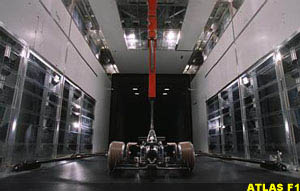
In each tunnel run, the model is automatically moved through four different ride heights, to simulate straight running, acceleration and braking, and to analyse the car's stability. Real time data covering properties such as lift (separated front and rear), drag, and aerodynamic centre of pressure is constantly taken from the model, and averaged for each set of ride heights during the run. This averaged data is then studied by the Aerodynamicist for trends showing the performance of the new part under test, or showing a possible problem such as something coming loose leading to false results. Based on this data, the part is rejected, re-tested, or modified for further testing.
Much use of plastacine used to be made in a wind tunnel - yes plastacine! In the development of a car for the following season, the aerodynamicists had ideas and developed them at the tunnel by molding plastacine and using chopped up carbon fibre pieces or whatever was around to test their theory on the car. Although not entirely accurate, this was a good method to take a look-see and assess whether it was worth pursuing that idea further by designing and manufacturing a more accurate piece before the following test. In doing this, much time was saved in the drawing office and model shop by avoiding devices that would not work. This process was also used when developing the car for the following year.
With more automated manufacturing processes, it is now possible to process a greater number of parts, so there is no need to use the plastacine, 'cut and shut' routine. This removes the possibility of erroneous results from ad-hoc modifications, and also eliminates the need for reverse engineering - working out how to draw the physical modifications made in the wind tunnel. However, the new methods make the job of the aerodynamicist less dynamic, for although he still analyses the data after every run, that doesn't affect the test itself, and it will always run to a planned timetable.
It is clear that wind tunnel testing is responsible for the development and set-up of the car, and with aerodynamics becoming more and more the most critical element, the work done here determines, and limits much of the cars design.
Previous Parts in this Series: Parts 1 & 2 | Part 3 | Part 4A | Part 4B | Part 4C | Part 5A | Part 5B | Part 6A | Part 6B
|
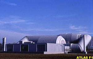 To test and develop aerodynamics, every team from the front to the back of the grid spends time in the wind tunnel, where air is blown over the car, rather than the car driving through the air on the race track. It does, however, create the same effect. Tunnels are expensive, and require a rolling road to simulate the airflow around the car effectively. For this reason, full size tunnels are not used - it is currently not possible to run a rolling road at the required full scale speeds. Therefore, teams use scale models, with sizes ranging from 1/3 scale (33%), up to 1/2 scale (50%). The larger the model, the more accurate the results, as parts can only be manufactured to a certain accuracy, and with larger parts, any inaccuracies are less significant. However, parts are often made many times over for some areas of the car to allow modifications, so as sizes increase, more material is used, manufacturing becomes more difficult, and costs rise. For this reason, a compromise must be considered as model scales further increase.
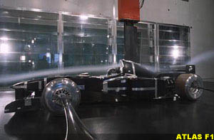
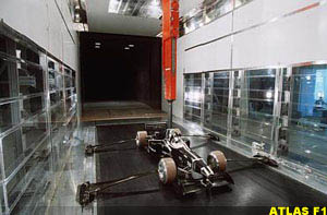 The tunnels are usually closed tunnels (air circulates around them in a continuous closed loop), and have massive fans and turning vanes which push air around at speeds of around 40m/s. The flow is straightened, by passing through a mesh, then travels through a contraction section to speed it up before it reaches the most important section of the tunnel - the test section. Once the air arrives here, the next thing to consider is the boundary layer - a thin layer of slow moving air next to any surface. It exists because air molecules on a surface are stationary, and there must be a gradual change in speed to reach that of the main airflow. The car doesn't experience a boundary layer on the racetrack, so it is important not to have a boundary layer in the wind tunnel, and complicated suction boundary layer control is used to remove it. In the test section, the car is attached, vertically, to a large balance which measures the forces on it, and sits on a rolling road which is matched to the wind speed.
 As well as development work, set-up work is done in the tunnel to create 'aero-maps' which, for example, show the performance of each rear wing element in terms of lift and drag, and tell which is most efficient to use in setting up the car for a certain downforce level. These are then taken to the Grands Prix by Race Engineers as an aid to the aerodynamic set-up of the car.
 Here, the initial base is the current car, and modifications are performed on it in a form of evolution. By using wood to construct the main body of the model, areas could be carved and sculpted by the model makers to create new shapes, and designs were available to return to the original if the modification failed. In the development time - the last quarter of the year, the model would be seen for a long time in wood and plastacine! When a more reliable piece was required (wood and plastacine move, making repeatability difficult, and making it hard to fit parts which once fitted together), slices and measurements could be taken from various model reference points and given to the designers, who would then make up a proper computer design of the part.
| Will Gray | © 2000 Kaizar.Com, Incorporated. |
| Send comments to: gray@atlasf1.com | Terms & Conditions |